Table of Contents
Introduction to Engineering Drawing Instruments
Drawings can be created quickly and precisely using drawing tools. The quality of the tools has a significant impact on how accurate the drawings are. It is simple to achieve desired accuracy using high-quality devices. Therefore, it is crucial to get instruments that are as high-quality as possible. This post provides introduction to engineering drawing instruments.
ड्रॉइंग टूल का उपयोग करके ड्रॉइंग को जल्दी और सटीक रूप से बनाया जा सकता है। चित्र कितने सटीक हैं, इस पर उपकरणों की गुणवत्ता का महत्वपूर्ण प्रभाव पड़ता है। उच्च-गुणवत्ता वाले उपकरणों का उपयोग करके वांछित सटीकता प्राप्त करना सरल है। इसलिए, ऐसे उपकरण प्राप्त करना महत्वपूर्ण है जो यथासंभव उच्च गुणवत्ता वाले हों।
The following are the minimal drawing equipment and other drawing materials that every student must have: Watch Video on Introduction to Engineering Drawing Instruments
1. Drawing board
2. T-square
3. Set-squares – 45° and 30°- 60°
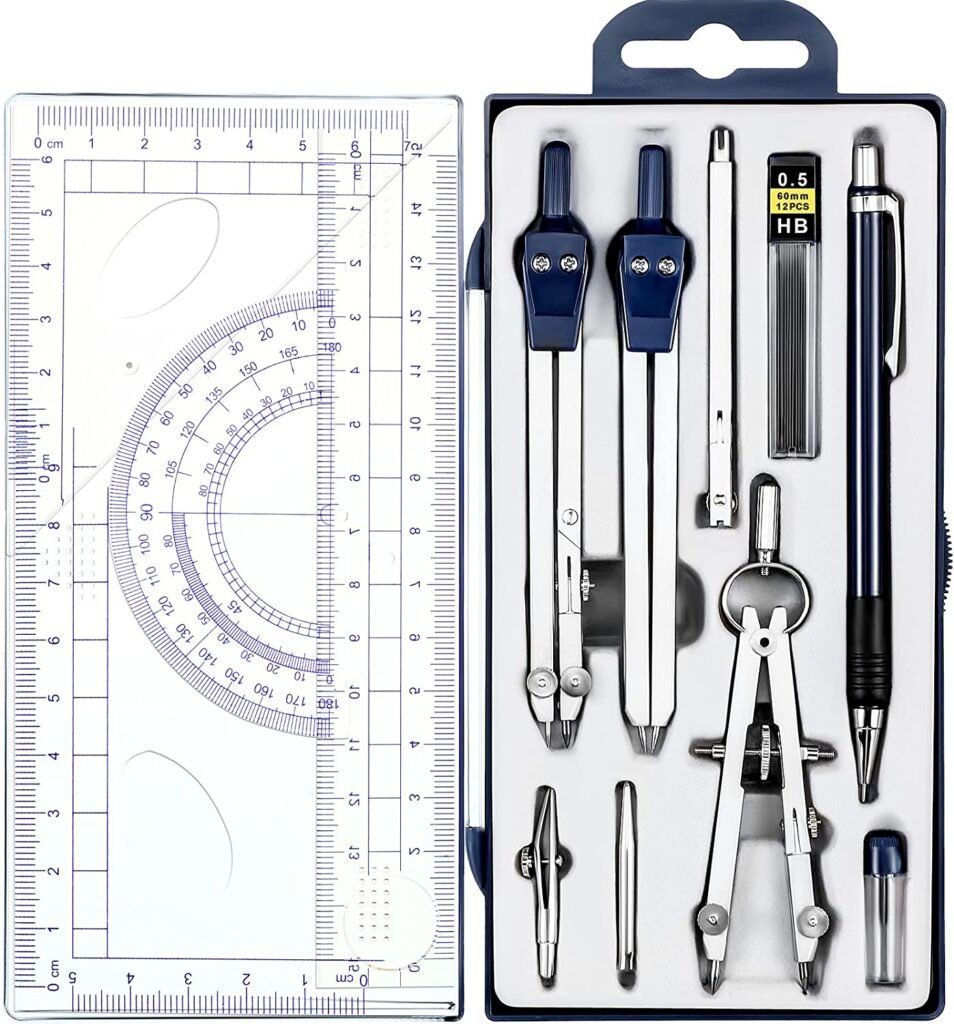
4. Drawing instrument box, containing:
(i) Large-size compass with inter-changeable pencil and pen legs
(ii) Lengthening bar
(iii) Small bow compass
(iv) Large-size divider
(v) Small bow divider
(vi) Small bow ink-pen
(vii) Inking pen
5. Scales
6. Protractor
7. French curves
8. Drawing papers
9. Drawing pencils
10. Sand-paper block
11. Eraser (Rubber)
12. Drawing pins, clips or adhesive tapes
13. Duster
14. Drafting machine
15. Roll-n-draw.
निम्नलिखित न्यूनतम ड्राइंग उपकरण और अन्य ड्राइंग सामग्री हैं जो प्रत्येक छात्र के पास होनी चाहिए: इंजीनियरिंग ड्राइंग इंस्ट्रूमेंट्स के परिचय पर वीडियो देखें
1. ड्राइंग बोर्ड
2. टी-स्क्वायर
3. सेट-स्क्वायर – 45° और 30°- 60°
4. ड्राइंग इंस्ट्रूमेंट बॉक्स, जिसमें:
(i) अंतर-परिवर्तनीय पेंसिल और पेन लेग्स के साथ बड़े आकार का कंपास
(ii) बार को लंबा करना
(iii) छोटा धनुष कम्पास
(iv) बड़े आकार का विभक्त
(v) छोटा धनुष विभक्त
(vi) छोटा धनुष स्याही-कलम
(vii) इंकिंग पेन
5. पैमाना (स्केल)
6. चांदा
7. फ्रेंच कर्व्स
8. ड्राइंग पेपर
9. ड्राइंग, पेंसिल
10. सैंड-पेपर ब्लॉक
11. रबड़ (रबर)
12. ड्राइंग पिन, क्लिप या चिपकने वाला टेप
13. डस्टर
14. ड्रॉफ्टिंग मशीन
15. रोल-एन-ड्रा।
1. Drawing board/1. ड्राइंग बोर्ड
The drawing board is rectangular in shape and consists of 25 mm thick strips of well-seasoned soft wood. Two battens cleat it at the rear to prevent warping. One of the board’s edges is designated as the working edge, along which the T-square is to slide. As a result, it should be precisely straight. This edge is grooved over the length of some boards, and a perfectly straight ebony edge is inserted inside this groove. This provides a more accurate and long-lasting guide for the T-square to glide on. (Watch Video on Use of Engineering Drawing Instruments)
Drawing boards come in a variety of sizes. Its choice is determined on the size of the drawing paper to be used. Table 1 lists the sizes of drawing boards suggested by the Bureau of Indian Standards (IS:1444-1989).
The latest two sizes of the drawing boards are more convenient for use in schools and universities. Engineers’ and engineering firms’ drawing offices employ large-size boards. The drawing board is situated in front of the student on the table, with the working edge on his left side. It is more convenient if the tabletop slopes down toward the student.
ड्राइंग बोर्ड आकार में आयताकार होता है और इसमें अच्छी तरह से अनुभवी नरम लकड़ी की 25 मिमी मोटी पट्टियां होती हैं। युद्ध को रोकने के लिए दो बैटन इसे पीछे से साफ करते हैं। बोर्ड के किनारों में से एक को वर्किंग एज के रूप में नामित किया गया है, जिसके साथ टी-स्क्वायर को स्लाइड करना है। नतीजतन, यह बिल्कुल सीधा होना चाहिए। इस किनारे को कुछ बोर्डों की लंबाई में बनाया गया है, और इस खांचे के अंदर एक पूरी तरह से सीधा आबनूस किनारा डाला गया है। यह टी-स्क्वायर को ग्लाइड करने के लिए अधिक सटीक और लंबे समय तक चलने वाला गाइड प्रदान करता है। (इंजीनियरिंग आरेखण उपकरणों के उपयोग पर वीडियो देखें)
ड्राइंग बोर्ड विभिन्न आकारों में आते हैं। इसका चुनाव उपयोग किए जाने वाले ड्राइंग पेपर के आकार पर निर्धारित होता है। तालिका 1 में भारतीय मानक ब्यूरो (आईएस:1444-1989) द्वारा सुझाए गए ड्राइंग बोर्ड के आकार सूचीबद्ध हैं।
ड्राइंग बोर्ड के नवीनतम दो आकार स्कूलों और विश्वविद्यालयों में उपयोग के लिए अधिक सुविधाजनक हैं। इंजीनियरों और इंजीनियरिंग फर्मों के ड्राइंग कार्यालय बड़े आकार के बोर्ड लगाते हैं। ड्राइंग बोर्ड छात्र के सामने मेज पर स्थित होता है, जिसके बाईं ओर काम करने वाला किनारा होता है। यह अधिक सुविधाजनक है यदि टेबलटॉप छात्र की ओर ढलान करता है।

Table 1/तालिका 1

2. T-square/2. टी-स्क्वायर
A T-square is composed of durable wood. It is made up of two parts: the stock and the blade, which are linked at right angles by screws and pins. The stock is situated adjacent to the board’s working edge and is designed to move on it as needed. The blade is resting on the board’s surface. Its remote edge, which is typically bevelled, serves as the working edge and hence must be perfectly straight. The blade’s nearer edge is never used. The length of the blade is chosen to match the size of the drawing board. T-squares are now available in celluloid or plastic with an etched scale. (Watch Video on Use of Engineering Drawing Instruments)
एक टी-स्क्वायर टिकाऊ लकड़ी से बना होता है। यह दो भागों से बना है: स्टॉक और ब्लेड, जो शिकंजा और पिन द्वारा समकोण पर जुड़े हुए हैं। स्टॉक बोर्ड के कामकाजी किनारे के निकट स्थित है और इसे आवश्यकतानुसार आगे बढ़ने के लिए डिज़ाइन किया गया है। ब्लेड बोर्ड की सतह पर टिका हुआ है। इसका दूरस्थ किनारा, जो आमतौर पर बेवल होता है, काम करने वाले किनारे के रूप में कार्य करता है और इसलिए पूरी तरह से सीधा होना चाहिए। ब्लेड के नजदीकी किनारे का कभी भी उपयोग नहीं किया जाता है। ब्लेड की लंबाई को ड्राइंग बोर्ड के आकार से मेल खाने के लिए चुना जाता है। टी-स्क्वायर अब सेल्युलाइड या प्लास्टिक में एक नक़्क़ाशीदार पैमाने के साथ उपलब्ध हैं।

Uses/उपयोग (इंजीनियरिंग आरेखण उपकरणों के उपयोग पर वीडियो देखें)
(i) A T-square is a tool used to draw horizontal lines. The T-square stock is held firmly against the working edge of the board with the left hand, and the line is drawn from left to right, as shown in figure below. The pencil should be held slightly inclined in the direction of the line (i.e. to the right), with the pencil point as close to the working edge of the blade as feasible. Sliding the stock to the desired positions results in horizontal parallel fines.
(i) टी-स्क्वायर एक उपकरण है जिसका उपयोग क्षैतिज रेखाएँ खींचने के लिए किया जाता है। टी-स्क्वायर स्टॉक को बाएं हाथ से बोर्ड के कामकाजी किनारे के खिलाफ मजबूती से रखा जाता है, और रेखा बाएं से दाएं खींची जाती है, जैसा कि नीचे दिए गए चित्र में दिखाया गया है। पेंसिल को रेखा की दिशा में (यानी दाईं ओर) थोड़ा झुका हुआ होना चाहिए, पेंसिल बिंदु ब्लेड के कामकाजी किनारे के जितना संभव हो सके। स्टॉक को वांछित स्थिति में स्लाइड करने से क्षैतिज समानांतर जुर्माना होता है।

(ii) The T-working square’s edge is also used as a foundation for set-squares to create vertical, slanted, or mutually parallel lines. To ensure uniform lead wear, a pencil must be spun while drawing lines. The T-square should never be used on any edge other than the board’s working edge. Even when not in use, it should always be kept on the board.
(ii) टी-वर्किंग स्क्वायर के किनारे का उपयोग सेट-स्क्वायर के लिए लंबवत, तिरछी या परस्पर समानांतर रेखाएँ बनाने के लिए एक नींव के रूप में भी किया जाता है। एक समान लेड पहनने को सुनिश्चित करने के लिए, रेखाएँ खींचते समय एक पेंसिल को काता जाना चाहिए। टी-स्क्वायर का इस्तेमाल बोर्ड के कामकाजी किनारे के अलावा किसी भी किनारे पर नहीं किया जाना चाहिए। उपयोग में न होने पर भी इसे हमेशा बोर्ड पर रखना चाहिए।
(iii) To check the straightness of the T-working square’s edge, mark any two points A and B (figure below) spaced widely apart and carefully through them Using the working edge, draw a line. As demonstrated, flip the T-square upside down by dashed lines, and then draw another line through with the same edge identical two points The lines will not correspond if the edge is faulty. The defective edge should be planed or sandpapered to correct the error.

(iii) टी-वर्किंग स्क्वायर के किनारे की सीधीता की जांच करने के लिए, किन्हीं दो बिंदुओं ए और बी (नीचे दी गई आकृति) को व्यापक रूप से अलग करें और उनके माध्यम से सावधानी से काम करने वाले किनारे का उपयोग करके, एक रेखा खींचें। जैसा कि दिखाया गया है, टी-स्क्वायर को धराशायी लाइनों द्वारा उल्टा फ्लिप करें, और फिर एक ही किनारे के समान दो बिंदुओं के साथ एक और रेखा खींचें यदि किनारे दोषपूर्ण है तो रेखाएं मेल नहीं खातीं। त्रुटि को ठीक करने के लिए दोषपूर्ण किनारे की योजना बनाई जानी चाहिए या सैंडपेपर किया जाना चाहिए।
3. Set-squares – 45° and 30°- 60°/3. सेट-स्क्वायर – 45° और 30°- 60°
Wood, tin, celluloid, or plastic are used to make the set-squares. Transparent celluloid or plastic are typically utilised since they hold their shape and accuracy for a longer period of time. There are two types of set-squares in common use. A set-square has three angles, one of which is a right angle. The 30°-60° set-square with a length of 250 mm and the 45° set-square with a length of 200 mm are ideal for use in schools and colleges. (Watch Video on Use of Engineering Drawing Instruments)
सेट-स्क्वायर बनाने के लिए लकड़ी, टिन, सेल्युलाइड या प्लास्टिक का उपयोग किया जाता है। पारदर्शी सेल्युलाइड या प्लास्टिक का आमतौर पर उपयोग किया जाता है क्योंकि वे लंबे समय तक अपना आकार और सटीकता बनाए रखते हैं। सामान्य उपयोग में दो प्रकार के सेट-स्क्वायर हैं। एक सेट-स्क्वायर में तीन कोण होते हैं, जिनमें से एक समकोण होता है। 30°-60° सेट-स्क्वायर 250 मिमी की लंबाई के साथ और 45° सेट-स्क्वायर 200 मिमी की लंबाई के साथ स्कूलों और कॉलेजों में उपयोग के लिए आदर्श हैं।
Uses/उपयोग (इंजीनियरिंग आरेखण उपकरणों के उपयोग पर वीडियो देखें)
(i) Set-squares are used for all straight lines except horizontal lines, which are often drawn with a T-square. The T-square and set-square can be used to make vertical lines.
(ii) When used in conjunction with the T-square, lines at 30° or 60° angles with vertical or horizontal lines and 45° angles with 45° set-square can be drawn. When the two set-squares are used in tandem with the T-square, they form lines with angles of 15°, 75°, 105°, and so on.
(iii) The two set-squares can also be used to draw parallel straight lines in any place, not too far apart, as well as lines perpendicular to any line from any given point within or outside it.
(iv) Using set-squares and T-squares, a circle can be divided into six, eight, twelve, and twenty-four equal sections.
(i) सेट-स्क्वायर का उपयोग क्षैतिज रेखाओं को छोड़कर सभी सीधी रेखाओं के लिए किया जाता है, जिन्हें अक्सर टी-स्क्वायर के साथ खींचा जाता है। टी-स्क्वायर और सेट-स्क्वायर का उपयोग लंबवत रेखाएं बनाने के लिए किया जा सकता है।
(ii) जब टी-स्क्वायर के साथ संयोजन में उपयोग किया जाता है, तो ऊर्ध्वाधर या क्षैतिज रेखाओं के साथ 30° या 60° कोणों पर और 45° सेट-स्क्वायर के साथ 45° कोणों पर रेखाएँ खींची जा सकती हैं। जब दो सेट-स्क्वायर का उपयोग टी-स्क्वायर के साथ मिलकर किया जाता है, तो वे 15°, 75°, 105° इत्यादि के कोणों वाली रेखाएँ बनाते हैं।
(iii) दो सेट-स्क्वायर का उपयोग किसी भी स्थान पर समानांतर सीधी रेखाएँ खींचने के लिए भी किया जा सकता है, जो बहुत दूर न हों, साथ ही किसी भी रेखा के भीतर या बाहर किसी भी बिंदु से लंबवत रेखाएँ खींची जा सकती हैं।
(iv) सेट-स्क्वायर और टी-स्क्वायर का उपयोग करके, एक सर्कल को छह, आठ, बारह और चौबीस बराबर वर्गों में विभाजित किया जा सकता है।
4. Drawing instrument box/4. ड्राइंग इंस्ट्रूमेंट बॉक्स
4-(1) large-size compass with pencil and pen leg interchangeability (figure 4-1):
The compass is used to draw circles and circle arcs. It is made up of two legs that are hinged together at the top. A sharp needle is placed into one leg, while a pencil lead is inserted into the other leg. The lower section of the pencil leg is detachable and can be swapped out for a comparable piece that contains an inking pen. Knee joints are present in both legs. With the compass legs straight, you can draw circles up to 120 mm in diameter. To draw wider circles, both legs should be bent at the knee joints and perpendicular to the paper’s surface (figure 4-1).Because the needle must be put somewhat deeper into the paper, it is kept longer than the lead point. Figure 4-1 depicts the positioning of the pencil-lead relative to the needle, as well as the shape to which the lead should be ground. (Watch Video on Use of Engineering Drawing Instruments)
To draw a circle, adjust the opening of the compass’s legs to the desired radius. With the help of the left hand, hold the compass with the thumb and first two fingers of the right hand and lay the needle tip softly on the centre. Place the pencil point on the paper and swing the compass around the needle-leg with a clockwise, twist of the thumb and two fingers until the circle is complete. Keep the compass slightly tilted in the direction of rotation. When creating concentric circles, start with the smallest circle and work your way up.
4-(1) पेंसिल और पेन लेग इंटरचेंजबिलिटी के साथ बड़े आकार का कंपास (चित्र 4-1):
कम्पास का उपयोग वृत्त और वृत्त चाप बनाने के लिए किया जाता है। यह दो पैरों से बना होता है जो शीर्ष पर एक साथ टिका होता है। एक पैर में एक तेज सुई रखी जाती है, जबकि दूसरे पैर में एक पेंसिल लेड डाली जाती है। पेंसिल लेग का निचला भाग वियोज्य है और इसे एक तुलनीय टुकड़े के लिए स्वैप किया जा सकता है जिसमें एक इंकिंग पेन होता है। घुटने के जोड़ दोनों पैरों में मौजूद होते हैं। कम्पास के पैरों को सीधा करके, आप 120 मिमी व्यास तक के वृत्त खींच सकते हैं। चौड़े घेरे बनाने के लिए, दोनों पैरों को घुटने के जोड़ों पर मुड़ा हुआ होना चाहिए और कागज की सतह के लंबवत होना चाहिए (चित्र 4-1)।
चूँकि सुई को कागज़ में थोड़ा गहरा रखना चाहिए, इसलिए इसे सीसे के बिंदु से अधिक समय तक रखा जाता है। चित्र 4-1 सुई के सापेक्ष पेंसिल-सीसा की स्थिति को दर्शाता है, साथ ही उस आकार को भी दर्शाता है जिस पर सीसा जमीन पर होना चाहिए।
एक वृत्त खींचने के लिए, कम्पास के पैरों के उद्घाटन को वांछित त्रिज्या में समायोजित करें। बायें हाथ की सहायता से कंपास को अंगूठे और दाहिने हाथ की पहली दो अंगुलियों से पकड़ें और सुई की नोक को धीरे से बीच में रखें। पेंसिल पॉइंट को कागज़ पर रखें और सुई-पैर के चारों ओर कम्पास को दक्षिणावर्त घुमाएँ, अंगूठे और दो अंगुलियों को तब तक घुमाएँ जब तक कि चक्र पूरा न हो जाए। कंपास को घुमाने की दिशा में थोड़ा झुका कर रखें। संकेंद्रित वृत्त बनाते समय, सबसे छोटे वृत्त से शुरू करें और अपने तरीके से काम करें। (इंजीनियरिंग आरेखण उपकरणों के उपयोग पर वीडियो देखें)
4-(2) lengthening bar:
The lengthening bar is used to draw circles with radiuses greater than 150 mm. The extending bar is installed in place of the lower part of the pencil leg. The removed component is then inserted at the end of the lengthening bar, lengthening the pencil leg (figure 4-2 ). While drawing huge circles, it is frequently necessary to guide the pencil leg with the other hand. (Watch Video on Use of Engineering Drawing Instruments)
4-(2) लंबी पट्टी:
लम्बी पट्टी का उपयोग 150 मिमी से अधिक त्रिज्या वाले वृत्त खींचने के लिए किया जाता है। पेंसिल लेग के निचले हिस्से के स्थान पर एक्सटेंडिंग बार स्थापित किया गया है। फिर हटाए गए घटक को पेंसिल लेग को लंबा करते हुए लंबी पट्टी के अंत में डाला जाता है (चित्र 4-2)। विशाल वृत्त बनाते समय, दूसरे हाथ से पेंसिल पैर को निर्देशित करना अक्सर आवश्यक होता है।
4-(3) Small bow compass:
Used for drawing small circles and arcs of less than 25 mm radius, and especially when drawing a large number of small circles of the same diameter (figure 4-3).
Curves drawn using a compass should be the same shade of grey as straight lines. It is difficult to apply the same amount of pressure to the compass lead as to a pencil.
To ensure uniform blackness in all lines, it is preferable to use a slightly softer kind of lead (approximately one grade lower, HB or HJ in the compass than the pencil used for drawing straight lines).
4-(3) छोटा धनुष कम्पास:
25 मिमी से कम त्रिज्या के छोटे वृत्त और चाप खींचने के लिए उपयोग किया जाता है, और विशेष रूप से जब एक ही व्यास के बड़ी संख्या में छोटे वृत्त खींचते हैं (आकृति 4-3)।
कम्पास का उपयोग करके खींचे गए वक्र सीधी रेखाओं के समान भूरे रंग के होने चाहिए। एक पेंसिल के रूप में कंपास लीड पर उतना ही दबाव लागू करना मुश्किल है।
सभी पंक्तियों में एक समान कालापन सुनिश्चित करने के लिए, थोड़ा नरम प्रकार की सीसा (सीधी रेखा खींचने के लिए उपयोग की जाने वाली पेंसिल की तुलना में कंपास में लगभग एक ग्रेड कम, एचबी या एचजे) का उपयोग करना बेहतर होता है।
4-(4) large-size divider:
The divider features two hinged legs at the upper end and steel pins at both bottom ends, but it lacks knee joints (figure 4-4).
Most instrument boxes include a needle attachment that may be swapped out for the compass’s pencil section, changing it into a divider.
Dividers are used to: (i) divide curved or straight lines into the desired number of equal portions, (ii) move dimensions from one part of the drawing to another, and (iii) set-off given distances from the scale to the drawing.
They are highly useful for establishing equal distances around a given point or along a given line.
4-(4) बड़े आकार के डिवाइडर:
डिवाइडर में ऊपरी सिरे पर दो टिका हुआ पैर और नीचे के दोनों सिरों पर स्टील की पिन होती है, लेकिन इसमें घुटने के जोड़ों की कमी होती है (चित्र 4-4)।
अधिकांश इंस्ट्रूमेंट बॉक्स में एक सुई अटैचमेंट शामिल होता है जिसे कम्पास के पेंसिल सेक्शन के लिए स्वैप किया जा सकता है, इसे डिवाइडर में बदल सकता है।
डिवाइडर का उपयोग किया जाता है: (i) घुमावदार या सीधी रेखाओं को वांछित संख्या में समान भागों में विभाजित करने के लिए, (ii) ड्राइंग के एक हिस्से से दूसरे हिस्से में आयामों को स्थानांतरित करने के लिए, और (iii) स्केल से ड्राइंग तक की दूरी को सेट-ऑफ़ करें। .
वे किसी दिए गए बिंदु के आसपास या किसी दी गई रेखा के साथ समान दूरी स्थापित करने के लिए अत्यधिक उपयोगी होते हैं।
4-(5) Small bow divider:
A nut adjusts the small bow divider, which is highly useful for marking minute divisions and a large number of short equal distances.
4-(5) छोटा धनुष विभक्त:
एक नट छोटे धनुष विभक्त को समायोजित करता है, जो कि मिनट के विभाजन और बड़ी संख्या में छोटी समान दूरी को चिह्नित करने के लिए अत्यधिक उपयोगी है।
(6) Small bow Ink Pen:
This pen is used to create small circles and arcs in ink.
(6) छोटा धनुष स्याही पेन:
इस पेन का उपयोग स्याही में छोटे वृत्त और चाप बनाने के लिए किया जाता है।
4-(7) Inking pen (figure 4-5): Use this to make straight lines and noncircular arcs in ink. It is made up of a pair of steel nibs attached to a metal or ivory holder. Ink is filled between the two nibs to a length of about 6 mm using a quill that is normally attached to the cork of the ink bottle. The screw 5 is used to regulate the space between the nibs, through which the ink flows and which determines the thickness of the line.
The pen should be kept slanted at about 60° with the paper in the direction of drawing the line, with the nib ends slightly away from the edge of the T-square or set-square. The screw should be placed on the side, away from the T-square.
Because the ink dries quickly, the pen should be used as soon as it is filled. The interior faces of the nibs should be cleaned on a regular basis to allow the ink to flow freely and to preserve line thickness uniformity. Never allow the ink to dry within the pen. The pen should never be dipped in ink since there should be no ink on the outside of the nibs.
In order to draw huge circles and circular arcs, use the inking attachment instead of the pencil leg in the compass.
4-(7) इंकिंग पेन (आकृति 4-5):
इसका उपयोग स्याही में सीधी रेखाएं और गैर-गोलाकार चाप बनाने के लिए करें। यह धातु या हाथीदांत धारक से जुड़ी स्टील निब की एक जोड़ी से बना होता है। स्याही दो निबों के बीच लगभग 6 मिमी की लंबाई तक एक क्विल का उपयोग करके भरी जाती है जो आमतौर पर स्याही की बोतल के कॉर्क से जुड़ी होती है। स्क्रू 5 का उपयोग निब के बीच की जगह को विनियमित करने के लिए किया जाता है, जिसके माध्यम से स्याही बहती है और जो रेखा की मोटाई निर्धारित करती है।
कलम को रेखा खींचने की दिशा में कागज के साथ लगभग 60° पर तिरछा रखा जाना चाहिए, साथ ही निब टी-स्क्वायर या सेट-स्क्वायर के किनारे से थोड़ा दूर समाप्त होता है। पेंच को टी-स्क्वायर से दूर, किनारे पर रखा जाना चाहिए।
चूंकि स्याही जल्दी सूख जाती है, इसलिए पेन को भरते ही इस्तेमाल करना चाहिए। स्याही को स्वतंत्र रूप से बहने देने और लाइन की मोटाई एकरूपता बनाए रखने के लिए निब के आंतरिक चेहरों को नियमित रूप से साफ किया जाना चाहिए। पेन के अंदर की स्याही को कभी भी सूखने न दें। पेन को कभी भी स्याही में नहीं डुबोना चाहिए क्योंकि निब के बाहर स्याही नहीं होनी चाहिए।
विशाल वृत्त और वृत्ताकार चाप खींचने के लिए, कंपास में पेंसिल लेग के बजाय इंकिंग अटैचमेंट का उपयोग करें।
5. Scales/5. पैमाना (स्केल)
Wood, steel, celluloid, plastic, and card board are all used to make scales. Stainless-steel scales last longer. Scales can be flat or triangular in shape. Flat scales 15 cm long and 2 cm wide or 30 cm long and 3 cm wide are commonly used. They are typically 1 mm thick. Longer edges of scales with more thickness are bevelled. This aids in precisely marking measures from the scale to the drawing paper. Both the longer edges of the scales are marked with centimetre divisions, which are further subdivided into millimetre divisions. (Watch Video on Use of Engineering Drawing Instruments)
The scale is used to translate an object’s true or relative dimensions to the drawing. It is positioned with its edge on the line on which measures are to be marked, and the marking is done with a fine pencil point from directly above the appropriate division. Never use the scale as a straight edge for drawing lines. The cardboard scales come in a package of eight scales. They are numbered from M1 to M8.
लकड़ी, स्टील, सेल्युलाइड, प्लास्टिक और कार्ड बोर्ड सभी का उपयोग तराजू बनाने के लिए किया जाता है। स्टेनलेस स्टील के तराजू लंबे समय तक चलते हैं। तराजू आकार में सपाट या त्रिकोणीय हो सकते हैं। आमतौर पर 15 सेमी लंबे और 2 सेमी चौड़े या 30 सेमी लंबे और 3 सेमी चौड़े फ्लैट तराजू का उपयोग किया जाता है। वे आम तौर पर 1 मिमी मोटे होते हैं। अधिक मोटाई वाले तराजू के लंबे किनारों को बेवल किया जाता है। यह स्केल से लेकर ड्राइंग पेपर तक के मापों को सटीक रूप से चिह्नित करने में सहायता करता है। तराजू के दोनों लंबे किनारों को सेंटीमीटर डिवीजनों के साथ चिह्नित किया गया है, जिन्हें आगे मिलीमीटर डिवीजनों में विभाजित किया गया है। (इंजीनियरिंग आरेखण उपकरणों के उपयोग पर वीडियो देखें)
स्केल का उपयोग किसी वस्तु के वास्तविक या सापेक्ष आयामों को ड्राइंग में अनुवाद करने के लिए किया जाता है। यह उस रेखा पर इसके किनारे के साथ स्थित है जिस पर उपायों को चिह्नित किया जाना है, और अंकन सीधे उपयुक्त विभाजन के ऊपर से एक ठीक पेंसिल बिंदु के साथ किया जाता है। रेखा खींचने के लिए पैमाने का उपयोग कभी भी सीधे किनारे के रूप में न करें। कार्डबोर्ड स्केल आठ स्केल के पैकेज में आते हैं। इनकी संख्या M1 से M8 तक होती है।
6. Protractor/6. चांदा
A protractor is typically made of wood, tin, or celluloid. Transparent celluloid protractors are widely used. They have a flat, circular or semi-circular form. The most common type of protractor is semi-circular and has a diameter of around 100 mm. Its circumferential edge is divided to one degree divisions, numbered every ten degrees, and readable from both ends. The base of the protractor is the diameter of the semi-circle (i.e. the straight line 0-180°), and its centre O is designated by a line perpendicular to it. (Watch Video on Use of Engineering Drawing Instruments)
The protractor is used to draw or measure angles that the set-squares cannot draw. The protractor can be used to divide a circle into any number of equal segments.
एक चांदा आमतौर पर लकड़ी, टिन या सेल्युलाइड से बना होता है। पारदर्शी सेल्युलाइड प्रोट्रैक्टर व्यापक रूप से उपयोग किए जाते हैं। उनके पास एक सपाट, गोलाकार या अर्ध-गोलाकार रूप है। सबसे आम प्रकार का चांदा अर्ध-गोलाकार है और इसका व्यास लगभग 100 मिमी है। इसकी परिधि के किनारे को एक डिग्री डिवीजनों में विभाजित किया गया है, हर दस डिग्री पर गिना जाता है, और दोनों सिरों से पढ़ा जा सकता है। चांदे का आधार अर्ध-वृत्त का व्यास है (अर्थात सीधी रेखा 0-180°), और इसका केंद्र O इसके लंबवत एक रेखा द्वारा निर्दिष्ट है। (इंजीनियरिंग आरेखण उपकरणों के उपयोग पर वीडियो देखें)
प्रोट्रैक्टर का उपयोग उन कोणों को खींचने या मापने के लिए किया जाता है जो सेट-स्क्वायर नहीं खींच सकते। प्रोट्रैक्टर का उपयोग किसी वृत्त को समान खंडों में विभाजित करने के लिए किया जा सकता है।
7. French curves/7. फ्रेंच कर्व्स
Wood, plastic, and celluloid are used to create French curves. They come in a variety of shapes, one of which is depicted in figure 4-8. These curves are also carved in the middle of several set-squares. French curves are used to draw curves that a compass cannot draw. First, a faint freehand curve is drawn through the known points. The french curve is then used to find the longest possible curves that exactly coincide with the freehand curve. Finally, using the french curve, a beautiful continuous curve is constructed. It is important to ensure that no corners form anywhere within the drawn curve. (Watch Video on Use of Engineering Drawing Instruments)
फ्रेंच वक्र बनाने के लिए लकड़ी, प्लास्टिक और सेल्युलाइड का उपयोग किया जाता है। वे कई प्रकार के आकार में आते हैं, जिनमें से एक को चित्र 4-8 में दर्शाया गया है। इन वक्रों को कई सेट-स्क्वायर के बीच में भी उकेरा गया है। फ्रेंच वक्रों का उपयोग उन वक्रों को खींचने के लिए किया जाता है जिन्हें एक कंपास नहीं खींच सकता। सबसे पहले, ज्ञात बिंदुओं के माध्यम से एक बेहोश मुक्तहस्त वक्र खींचा जाता है। फ्रेंच वक्र का उपयोग तब सबसे लंबे संभव वक्रों को खोजने के लिए किया जाता है जो कि मुक्तहस्त वक्र के साथ बिल्कुल मेल खाते हैं। अंत में, फ्रेंच वक्र का उपयोग करके, एक सुंदर निरंतर वक्र का निर्माण किया जाता है। यह सुनिश्चित करना महत्वपूर्ण है कि खींचे गए वक्र के भीतर कहीं भी कोई कोना न बने। (इंजीनियरिंग आरेखण उपकरणों के उपयोग पर वीडियो देखें)
8. Drawing papers/8. ड्राइंग पेपर
There are numerous types of drawing papers available. The paper used for everyday pencil drawings should be robust and durable. It should be as white and uniform in thickness as feasible. The fibres of the rubber eraser should not disintegrate when used on it. For drawings that will be inked and kept for a long period, good quality paper with a flat surface should be used. It should be tight enough so that the ink does not spread. For drawings from which tracings are to be made, thin and low-quality paper may be utilised.
Figure 4-9 shows the standard sizes of drawing sheets suggested by the Bureau of Indian Standards (B.I.S.). One square metre is the surface area of an A0 size. The next format size (from A0 to A5) is obtained by halving the length or doubling the width. The areas of the two subsequent sizes are proportional to one another. (Watch Video on Use of Engineering Drawing Instruments)
कई प्रकार के ड्राइंग पेपर उपलब्ध हैं। प्रतिदिन पेंसिल के चित्र बनाने के लिए उपयोग किया जाने वाला कागज मजबूत और टिकाऊ होना चाहिए। यह यथासंभव सफेद और मोटाई में एक समान होना चाहिए। रबर इरेज़र के रेशों का उपयोग करते समय उन्हें विघटित नहीं करना चाहिए। जिन चित्रों पर स्याही लगी होगी और जो लंबे समय तक रखे जाएंगे, उनके लिए एक सपाट सतह के साथ अच्छी गुणवत्ता वाले कागज का उपयोग किया जाना चाहिए। यह इतना टाइट होना चाहिए कि स्याही न फैले। जिन रेखाचित्रों से ट्रेसिंग की जानी है, उनके लिए पतले और निम्न गुणवत्ता वाले कागज का उपयोग किया जा सकता है। (इंजीनियरिंग आरेखण उपकरणों के उपयोग पर वीडियो देखें)
चित्र 4-9 भारतीय मानक ब्यूरो (बी.आई.एस.) द्वारा सुझाई गई ड्राइंग शीट के मानक आकार को दर्शाता है। एक वर्ग मीटर A0 आकार का सतह क्षेत्र है। अगला प्रारूप आकार (A0 से A5 तक) लंबाई को आधा करके या चौड़ाई को दोगुना करके प्राप्त किया जाता है। बाद के दो आकारों के क्षेत्र एक दूसरे के समानुपाती होते हैं।
9. Drawing pencils/9. ड्राइंग, पेंसिल
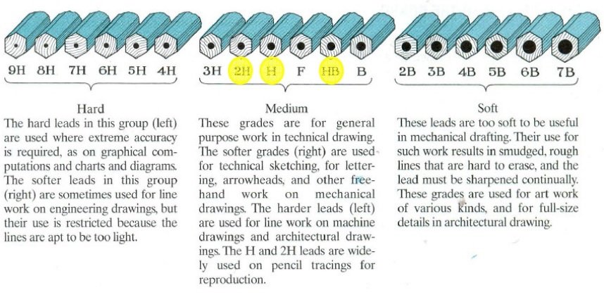
The quality of the pencils used has a significant impact on the accuracy and attractiveness of a drawing. It is quite difficult to draw lines of uniform shade and thickness with inexpensive and low-quality pencils. A pencil lead’s grade is typically indicated by figures and letters marked at one of its ends. The letters HB stand for medium grade. The value of the figure put in front of the letter H, i.e. 2H, 3H, 4H, etc., indicates the increase in hardness. Similarly, the grade softens according to the figure placed in front of the letter B, i.e. 28, 38, 48, and so on.
The first lines of a drawing should be drawn with a H or 2H pencil, very gently, so that the lines are faint and superfluous or excess lines can be quickly erased. The final fair work can be done with tougher pencils, such as 3H and higher. Hardgrade pencils make it easier to draw lines of uniform thickness and darkness.
For lettering and dimensioning, H and HB pencils are preferable. Soft-grade pencils, such as HB, should be used for freehand sketching if extensive erasing is required.
Care should be made when repairing the pencil and sharpening the lead, as this has a great impact on the consistency of line thickness. The lead can be refined into two forms: (Watch Video on Use of Engineering Drawing Instruments)
Conical tip I and chisel edge (ii).
The conical point is used in sketching, lettering, and other similar tasks. Long thin lines of uniform thickness can be readily created with the chisel edge, making it perfect for drawing tasks. To prepare the pencil lead for drawing work, remove the wood from the end other than the one on which the grade is marked with a penknife, leaving about 10 mm of lead sticking out, as illustrated in figure 4-10a.
The chisel edge [figure 4-10b] is created by rubbing the lead flat on a sandpaper block, first on one side and then on the other by turning the pencil through a half circle. To make the conical end [figure 4-10c], rotate the pencil between the thumb and fingers while stroking the lead. The pencil lead should be rubbed on the sandpaper block on a regular basis (when sketching) to keep the chisel edge or pointed end sharp.
Mechanical clutch pencils with varied lead sizes and grades, such as 5 mm, 4 mm and H, 2H, HB, and so on, are available in addition to wooden pencils. Sharpening is not necessary with these pencils.
उपयोग की गई पेंसिलों की गुणवत्ता का ड्राइंग की सटीकता और आकर्षण पर महत्वपूर्ण प्रभाव पड़ता है। सस्ती और निम्न-गुणवत्ता वाली पेंसिल से एक समान छाया और मोटाई की रेखाएँ खींचना काफी कठिन है। एक पेंसिल लीड का ग्रेड आम तौर पर इसके एक छोर पर चिह्नित अंकों और अक्षरों द्वारा दर्शाया जाता है। एचबी अक्षर मध्यम ग्रेड के लिए खड़े हैं। H अक्षर के सामने रखी गई आकृति का मान, यानी 2H, 3H, 4H, आदि, कठोरता में वृद्धि को इंगित करता है। इसी तरह, ग्रेड बी अक्षर के सामने रखे गए आंकड़े के अनुसार नरम हो जाता है, यानी 28, 38, 48, और इसी तरह।
एक ड्राइंग की पहली पंक्तियों को एच या 2 एच पेंसिल के साथ बहुत धीरे से खींचा जाना चाहिए, ताकि रेखाएं फीकी और अनावश्यक हों या अतिरिक्त लाइनों को जल्दी से मिटाया जा सके। अंतिम निष्पक्ष कार्य कठिन पेंसिल, जैसे 3H और उच्चतर के साथ किया जा सकता है। हार्डग्रेड पेंसिल से समान मोटाई और अंधेरे की रेखाएं खींचना आसान हो जाता है। (इंजीनियरिंग आरेखण उपकरणों के उपयोग पर वीडियो देखें)
लेटरिंग और डाइमेंशन के लिए एच और एचबी पेंसिल बेहतर हैं। सॉफ्ट-ग्रेड पेंसिल, जैसे कि एचबी, का उपयोग फ्रीहैंड स्केचिंग के लिए किया जाना चाहिए यदि व्यापक मिटाने की आवश्यकता हो।
पेंसिल की मरम्मत करते समय और लेड को तेज करते समय सावधानी बरतनी चाहिए, क्योंकि इससे लाइन की मोटाई की स्थिरता पर बहुत प्रभाव पड़ता है। सीसा को दो रूपों में परिष्कृत किया जा सकता है:
शंक्वाकार टिप I और छेनी का किनारा (ii)।
शंक्वाकार बिंदु का उपयोग स्केचिंग, लेटरिंग और इसी तरह के अन्य कार्यों में किया जाता है। एक समान मोटाई की लंबी पतली रेखाएं छेनी के किनारे से आसानी से बनाई जा सकती हैं, जिससे यह ड्राइंग कार्यों के लिए एकदम सही हो जाती है। ड्राइंग के काम के लिए पेंसिल लेड तैयार करने के लिए, लकड़ी को उस छोर से हटा दें, जिस पर ग्रेड एक पेननाइफ के साथ चिह्नित है, लगभग 10 मिमी सीसा बाहर चिपका हुआ है, जैसा कि चित्र 4-10a में दिखाया गया है।
छेनी का किनारा [आकृति 4-10बी] एक सैंडपेपर ब्लॉक पर लेड फ्लैट को रगड़कर बनाया जाता है, पहले एक तरफ और फिर दूसरी तरफ पेंसिल को आधा सर्कल में घुमाकर। शंक्वाकार सिरे [आकृति 4-10सी] बनाने के लिए, पेंसिल को अंगूठे और उंगलियों के बीच घुमाते हुए सीसे को सहलाएं। छेनी के किनारे या नुकीले सिरे को नुकीले रखने के लिए पेंसिल लेड को नियमित रूप से (स्केचिंग करते समय) सैंडपेपर ब्लॉक पर रगड़ना चाहिए।
लकड़ी के पेंसिल के अलावा, 5 मिमी, 4 मिमी और एच, 2 एच, एचबी, और इसी तरह के विभिन्न आकार और ग्रेड के साथ मैकेनिकल क्लच पेंसिल उपलब्ध हैं। इन पेंसिलों से पैनापन करना आवश्यक नहीं है।
10. Sand-paper block/10. सैंड-पेपर ब्लॉक
It is made of a 150 mm × 50 mm x 12 mm thick wooden block with a piece of sandpaper pasted or nailed on roughly half of its length, as seen in figure 4-11.
When the sandpaper becomes dirty or worn out, it should be replaced. This block should always be kept nearby so that you can sharpen the pencil lead every few minutes. (Watch Video on Use of Engineering Drawing Instruments)
यह 150 मिमी × 50 मिमी x 12 मिमी मोटे लकड़ी के ब्लॉक से बना होता है, जिसकी लंबाई के लगभग आधे हिस्से पर सैंडपेपर का एक टुकड़ा चिपकाया जाता है, जैसा कि चित्र 4-11 में देखा गया है। (इंजीनियरिंग आरेखण उपकरणों के उपयोग पर वीडियो देखें)
जब सैंडपेपर गंदा या खराब हो जाता है, तो उसे बदल दिया जाना चाहिए। इस ब्लॉक को हमेशा पास में ही रखना चाहिए ताकि आप हर कुछ मिनट में पेंसिल लेड को तेज कर सकें।
11. Eraser (Rubber)/11. रबड़ (रबर)
Soft India-rubber erasers are the best choice for pencil drawings. It should be such that it does not damage the paper’s surface. Rubber should be used sparingly and with caution.
पेंसिल ड्रॉइंग के लिए सॉफ्ट इंडिया-रबर इरेज़र सबसे अच्छा विकल्प है। यह ऐसा होना चाहिए कि यह कागज की सतह को नुकसान न पहुंचाए। रबड़ का प्रयोग संयम से और सावधानी से करना चाहिए। (इंजीनियरिंग आरेखण उपकरणों के उपयोग पर वीडियो देखें)
12. Drawing pins, clips or adhesive tapes/12. ड्राइंग पिन, क्लिप या चिपकने वाला टेप
This is used to secure the drawing paper to the drawing board. The needle portion of the pin is often made of steel, but the head is typically made of plated mild steel or brass. Pins with 15 mm to 20 mm diameters and 1 mm thick flat heads manufactured of brass are very useful since they do not rust. Pins should be put such that the heads rest on the paper’s surface. Instead of pins, clips or adhesive tape are frequently utilised. (See Figure 4-11.) (Watch Video on Use of Engineering Drawing Instruments)
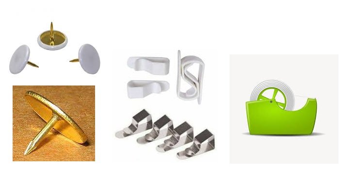
इसका उपयोग ड्राइंग पेपर को ड्राइंग बोर्ड पर सुरक्षित करने के लिए किया जाता है। पिन का सुई वाला हिस्सा अक्सर स्टील का बना होता है, लेकिन सिर आमतौर पर मढ़वाया हल्के स्टील या पीतल से बना होता है। 15 मिमी से 20 मिमी व्यास वाले पिन और पीतल से बने 1 मिमी मोटे फ्लैट हेड बहुत उपयोगी होते हैं क्योंकि वे जंग नहीं लगाते हैं। पिन ऐसे लगाए जाने चाहिए कि सिर कागज की सतह पर टिके रहें। पिन के बजाय, क्लिप या चिपकने वाली टेप का अक्सर उपयोग किया जाता है। (चित्र 4-11 देखें।) (इंजीनियरिंग आरेखण उपकरणों के उपयोग पर वीडियो देखें)
13. डस्टर/13. Duster
A duster made of a convenient size towel cloth is preferred. All tools and supplies should be thoroughly cleaned with the duster before beginning work. The rubber crumbs that accumulate after using the rubber should be swept away with a duster rather than by hand. The underside of the T-square and set-squares, as well as the drawing machine, should be cleaned on a regular basis. (Watch Video on Use of Engineering Drawing Instruments)
सुविधाजनक आकार के तौलिये के कपड़े से बने डस्टर को प्राथमिकता दी जाती है। काम शुरू करने से पहले सभी औजारों और आपूर्तियों को डस्टर से अच्छी तरह साफ कर लेना चाहिए। रबर का उपयोग करने के बाद जमा होने वाले रबर के टुकड़ों को हाथ से नहीं बल्कि डस्टर से साफ किया जाना चाहिए। टी-स्क्वायर और सेट-स्क्वायर के नीचे, साथ ही ड्राइंग मशीन को नियमित रूप से साफ किया जाना चाहिए। (इंजीनियरिंग आरेखण उपकरणों के उपयोग पर वीडियो देखें)
14. Drafting machine/14. ड्रॉफ्टिंग मशीन
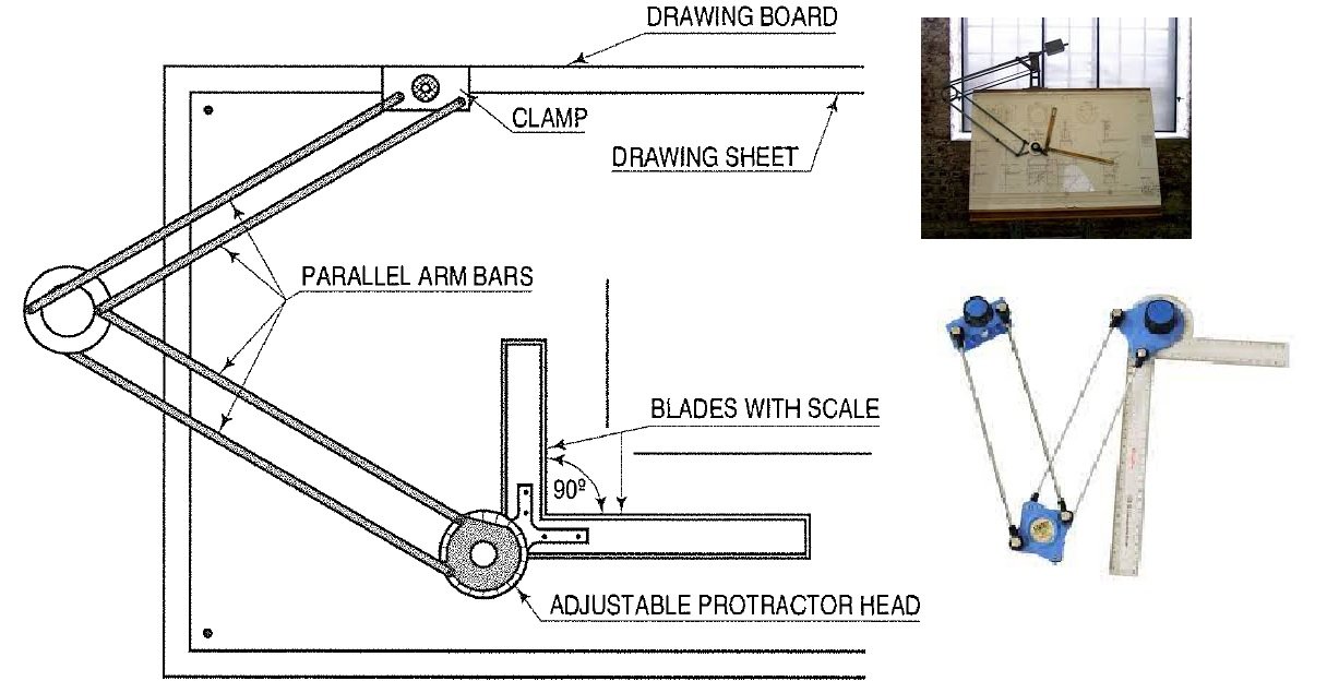
The drafting machine combines the benefits and uses of the T-square, set-squares, scales, and protractor. Its one end is screwed to the drawing board’s remote longer edge. An adjustable head with protractor markings is attached to the other end. The head is equipped with two transparent celluloid blades that are precisely positioned at perfect angles to each other.
The machine contains a mechanism that keeps the two blades parallel to their respective original positions regardless of where they are moved on the board. The blades are marked with scales and are utilised as straight edges. Because the blades on certain machines are detachable, a variety of scales can be employed. The protractor markings allow the blades to be positioned at any desired angle.
Thus, with this machine, horizontal, vertical, or inclined parallel lines of required lengths can be drawn anywhere on the sheet with great ease and efficiency. Drafting machines are very popular among college students and draughtsmen. (Watch Video on Use of Engineering Drawing Instruments)
ड्राफ्टिंग मशीन टी-स्क्वायर, सेट-स्क्वायर, स्केल और प्रोट्रैक्टर के लाभों और उपयोगों को जोड़ती है। इसका एक सिरा ड्राइंग बोर्ड के दूरस्थ लंबे किनारे पर खराब कर दिया जाता है। प्रोट्रैक्टर चिह्नों के साथ एक समायोज्य सिर दूसरे छोर से जुड़ा हुआ है। सिर दो पारदर्शी सेल्युलाइड ब्लेड से सुसज्जित है जो एक दूसरे से बिल्कुल सही कोण पर स्थित हैं। (इंजीनियरिंग आरेखण उपकरणों के उपयोग पर वीडियो देखें)
मशीन में एक तंत्र होता है जो दो ब्लेडों को उनकी संबंधित मूल स्थिति के समानांतर रखता है, भले ही उन्हें बोर्ड पर कहीं भी ले जाया गया हो। ब्लेड को तराजू से चिह्नित किया जाता है और सीधे किनारों के रूप में उपयोग किया जाता है। चूंकि कुछ मशीनों पर ब्लेड वियोज्य होते हैं, इसलिए विभिन्न प्रकार के पैमानों को नियोजित किया जा सकता है। प्रोट्रैक्टर मार्किंग ब्लेड को किसी भी वांछित कोण पर तैनात करने की अनुमति देता है।
इस प्रकार, इस मशीन के साथ, आवश्यक लंबाई की क्षैतिज, ऊर्ध्वाधर, या झुकी हुई समानांतर रेखाएं शीट पर कहीं भी बड़ी आसानी और दक्षता के साथ खींची जा सकती हैं। ड्राफ्टिंग मशीनें कॉलेज के छात्रों और ड्राफ्ट्समैन के बीच बहुत लोकप्रिय हैं।
15. Roll-n-draw/15. रोल-एन-ड्रा।
It is made up of a graduated roller, a 16-centimeter scale, and a protactor. It is perfect for drawing vertical, horizontal, parallel, and angled lines, as well as circles. (Watch Video on Use of Engineering Drawing Instruments)

यह एक स्नातक किए हुए शासक, एक 16-सेंटीमीटर पैमाने और एक चांदा से बना है। यह लंबवत, क्षैतिज, समानांतर और कोण वाली रेखाओं के साथ-साथ मंडलियों को खींचने के लिए एकदम सही है। (इंजीनियरिंग आरेखण उपकरणों के उपयोग पर वीडियो देखें)

