Knuckle Joint: Introduction, Application and Design Steps
Table of Contents
What is a knuckle joint?
A knuckle joint is a pin joint used to fasten two circular rods.
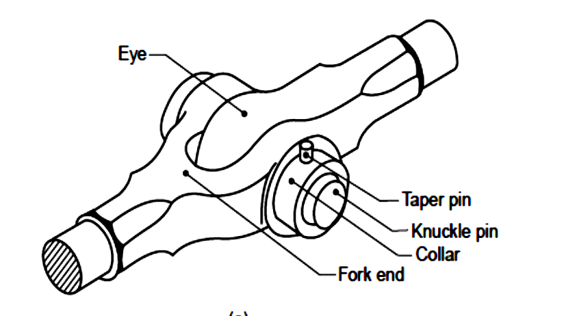
In this joint, one end of the rod is formed into an eye and the other into a fork (double eye).
For making the joint, the eye end of the rod is aligned with the fork end of the other, and then the pin is inserted through the holes and held in position by means of a collar and a taper pin.
Once the joint is made, the rods are free to swivel about the cylindrical pin.
Application of Knuckle Joint
Some of the Applications of the Knuckle Joint:
Air brake arrangement of locomotives.
Joints between the tie bars in roof trusses.
Joints between the links of a suspension bridge.
Joints in the valve mechanism of a reciprocating engine.
Fulcrum for the levers.
Joints between the links of a bicycle chain.
Click here to read the pdf
Design of knuckle Joint
It is assumed that the material for the rods and pins is the same, and the allowable stresses in tension, compression, and shear are given by σt, σc, and τ. [PDF]
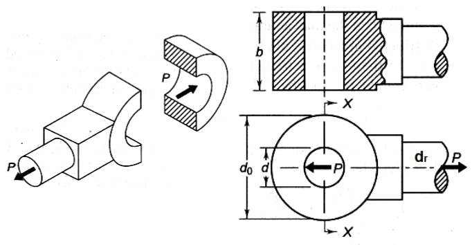
1. Tension Failure of rod at diameter d. [math](\frac{\pi }{4}{d_r^2}) \sigma_t=P[/math], Determine rod diameter d from this equation. 
2. Tension failure of the eye end. [math]{b}{(d_0-d)}\sigma_t=P[/math]
3. Tension Failure of the fork end. [math]{2a}{(d_0-d)}\sigma_t=P[/math]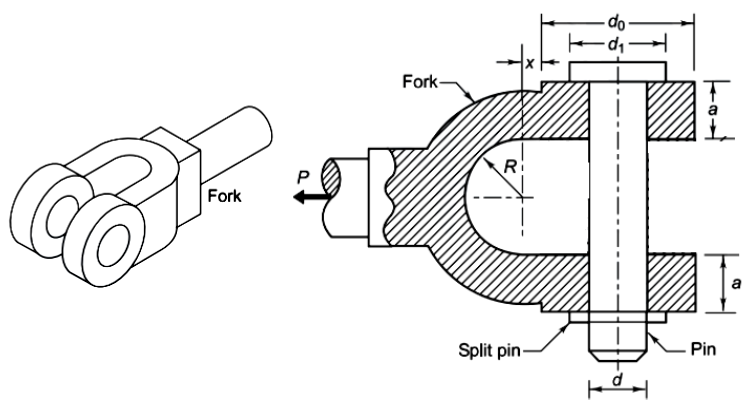
4. Shear failure of the knuckle pin. [math]{2}(\frac{\pi }{4}d^2)\tau=P[/math] 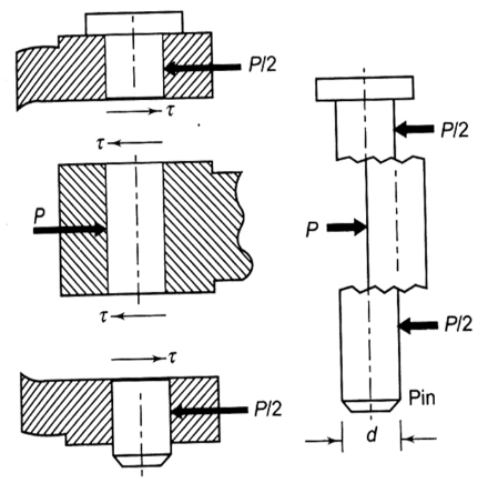
calculate the diameter d of the knuckle pin from this relation.
5. Compression failure of the knuckle pin at the fork end. [math]{2}{a}{d}\sigma_c=P [/math]
The value of a, i.e., the thickness of the fork end, is determined from this relation.
6. Compression failure of the knuckle pin at the eye end. [math]{b}{d}\sigma_c=P [/math]
The value of b is to be determined from this relation.
7. Shear failure of the eye end. [math]{b}{(d_0-d)}\tau=P [/math]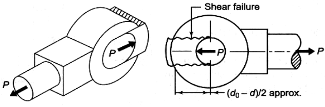
This relationship is used to check the working shear stress that has developed in the joint.
8. Shear failure of the fork end. [math]{2a}{(d_0-d)}\tau=P [/math] calculate d0 from this relation.
9. Bending of the knuckle pin.
It is assumed that the load acting on the pin is uniformly distributed in the eye end, but it is uniformly varying in two parts of the fork.
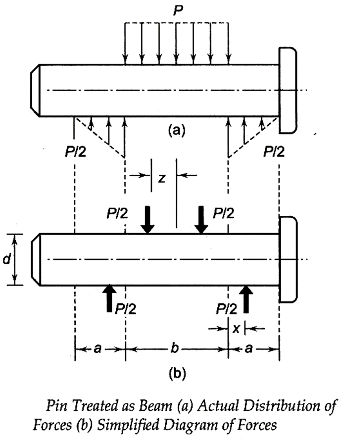
For triangular distribution of load between the pin and the fork,
[math]{x}=\frac{1 }{3}{a}[/math] also [math]{z}=\frac{1}{2}{(\frac{1}{2}{b})}=\frac{1}{4}{b} [/math]
The bending moment is maximum at the centre. It is given by [math]{M_b}=\frac{P }{2}[\frac{b}{2}+({x})]-\frac{P}{2}({z})[/math]
[math]{M_b}=\frac{P }{2}[\frac{b}{2}+\frac{a}{3}]-\frac{P}{2}(\frac{b}{4})[/math]
[math]{M_b}=\frac{P }{2}[\frac{b}{4}+\frac{a}{3}][/math]
Also [math]{I}=\frac{{\pi}{d^4}}{64}[/math], and [math]{y}=\frac{d}{2}[/math] therefore [math]{\sigma_b}=\frac{(M_b)y}{I}[/math] therefore [math]{\sigma_b}=\frac{\frac{P}{2}{[\frac{b}{4}+\frac{a}{3}]}{\frac{d}{2}}}{\frac{{\pi}{d^4}}{64}}[/math]
[math]{\sigma_b}={16P}\frac{{[\frac{b}{4}+\frac{a}{3}]}}{{\pi}{d^3}}[/math]
After determining all the parameters, finally check the bending stress of the knuckle pin using the above relation. If [math]{\sigma_b}<={\sigma_t} [/math], then design is safe; otherwise, design is failed.
[math]{\sigma_b}[/math] can be reduced by changing the value of d, since [math]{\sigma_b}[/math] is inversely proportional to the cube of d.
click here to watch the video lecture
References
-
ABDULLA SHARIF, Design of Machine Elements, Dhanpat Rai Publications (P) Ltd, New Delhi, 1995.
-
http://www.nptel.iitm.ac.in
-
https://machinedesign.top/content/Introduction%20to%20Machine%20Design
-
V. B. Bhandari, Design of Machine Elements, Third Ed., The McGraw-Hills Companies, New Delhi
-
S. KHURMI and J.K.GUPTA, A Text Book of Machine Design, S. Chand and company ltd., New Delhi, 2000.
Q & A
Q. 1. Design a knuckle joint to connect two steel rods in a circular cross section to carry an axial pull of 40 kN. All the components of the joint are to be made of steel.
Ans: click here to watch the solution in the video lecture.

