Cotter Joint – Introduction, Classification and Design Steps
Table of Contents
What is Cotter Joint ?
Introduction
A cotter is a flat wedge-shaped piece, made of steel. It is uniform in thickness but tapering in width, generally on one side; the usual taper being 1:30. The lateral (bearing) edges of the cotter and the bearing slots are generally made semi-circular instead of straight. This increases the bearing area and permits drilling while making the slots.
The cotter is locked in position by means of a screw. Cotter joints are used to connect two rods, subjected to tensile or compressive forces along their axes. These joints are not suitable where the members are under rotation.
Classification of Cotter Joint
The following are some of the commonly used cotter joints:
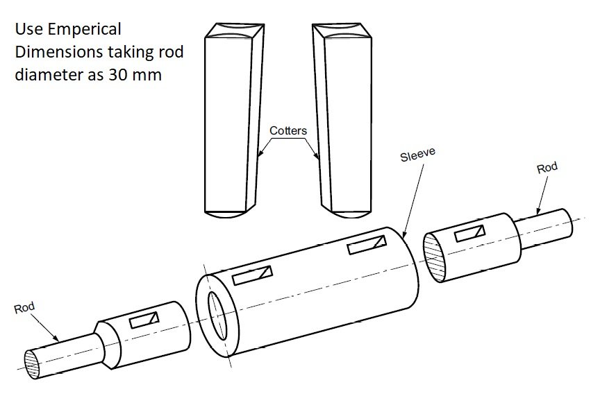
Cotter Joint With Sleeve:
This is the simplest of all cotter joints, used for fastening two circular rods. To make the joint, the rods are enlarged at their ends and slots are cut. After keeping the rods butt against each other, a sleeve with slots is placed over them. After aligning the slots properly, two cotters are driven-in through the slots, resulting in the joint.
The rod ends are enlarged to take care of the weakening effect caused by the slots. The slots in the rods and sleeve are made slightly wider than the width of cotter. The relative positions of the slots are such, that when a cotter is driven into its position, it permits wedging action and pulls the rod into the sleeve.
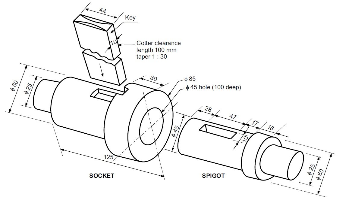
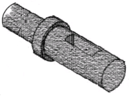
Cotter Joint With Spigot & Socket End
This joint is used to fasten two circular rods. In this, the rod ends are modified instead of using a sleeve. One end of the rod is formed into a socket and the other into a spigot and slots are cut. After aligning the socket and spigot ends, a cotter is driven-in through the slots, forming the joint.
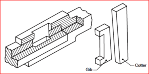
Cotter Joint with Gib:
This joint is generally used to connect two rods of square or rectangular cross-section. To make the joint, one end of the rod is formed into a U-fork, into which, the end of the other rod fits in. When a cotter is driven-in, the friction between the cotter and straps of the U-fork, causes the straps to open. This is prevented by the use of a gib.
A gib is also a wedge shaped piece of rectangular cross-section with two rectangular projections called lugs. One side of the gib is tapered and the other straight. The tapered side of the gib bears against the tapered side of the cotter such that, the outer edges of the cotter and gib as a unit are parallel. This facilitates making of slots with parallel edges, unlike the tapered edges in case of ordinary cotter joint. Further, the lugs bearing against the outer surfaces of the fork, prevents the opening tendency of the straps. For making the joint, first the gib is placed in position and then the cotter is driven-in. Click here to read in pdf
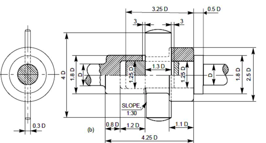
Design of Spigot and Socket Cotter Joint
If the allowable stresses in tension, compression, and shear for the socket, rod, and cotter are σt, σc, and τ, respectively, assuming that they are all made of the same material, we may write the following failure criteria: [PDF]
1. Tension Failure of rod at diameter d [math]\frac{\pi }{4}{d^2} \sigma_t=P[/math] Determine d from this equation.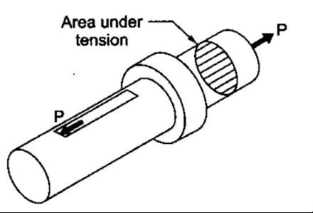
2. Tension Failure of spigot across the slot [math](\frac{\pi }{4}{d_2^2}-{d_2}{t})\sigma_t=P[/math]
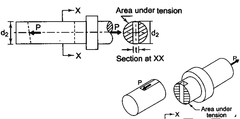
3. Crushing Failure of rod or cotter [math]{d_2}{t}\sigma_c=P[/math]
From above two equations calculate d2 and t.
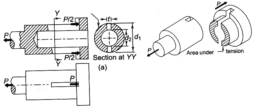
4. Tension Failure of Socket across slot. [math]\{\frac{\pi }{4}({d_1^2}-{d_2^2})-({d_1}-{d_2}){t}\}\sigma_t=P[/math]
calculate d1 from this relation by putting the value of d2 and t.
5. Shear Failure of Cotter [math]{2}{b}{t}\tau=P [/math]
the value of b i.e. mean width of cotter is determined from this relation.
6. Shear Failure of Spigot Rod end [math]{2}{a}{d_2}\tau=P [/math]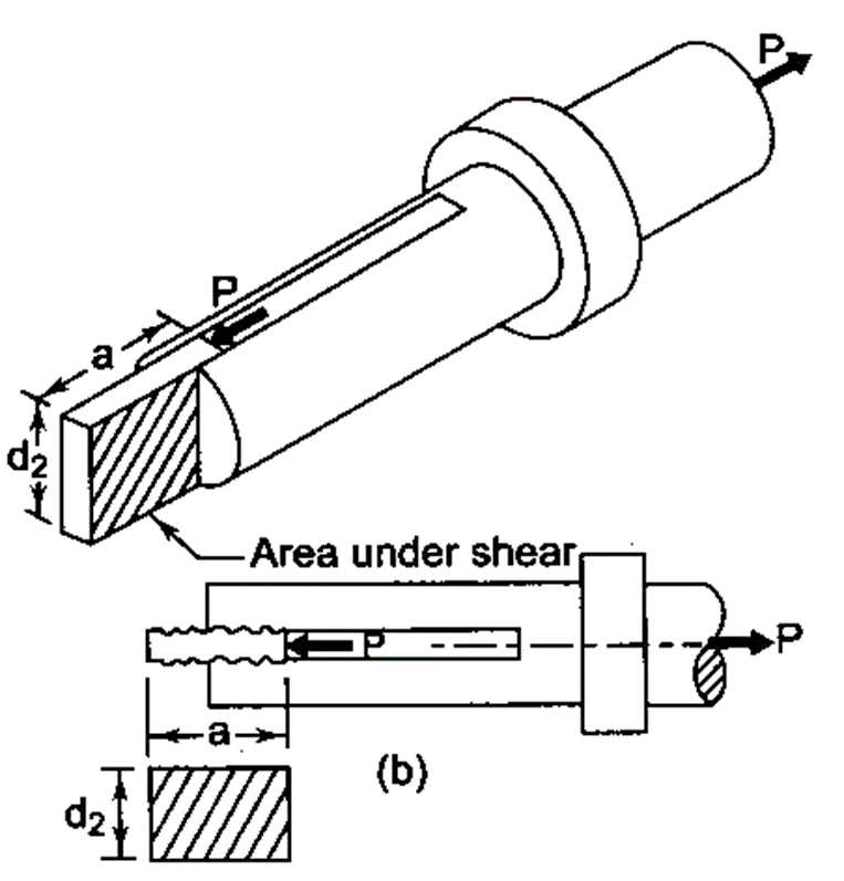
the value of a is determined from this relation.
7. Shear Failure of Socket end [math]{2}{c}{(d_4-d_2)}\tau=P [/math]
This relation is used to calculate the value of c after putting the value of d4.
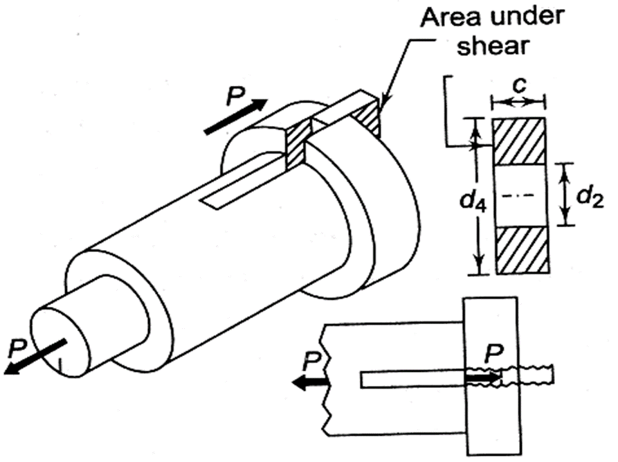
8. Crushing Failure of Socket or cotter [math]{(d_4-d_2)}{t}\sigma_c=P [/math]
calculate d4 from this relation
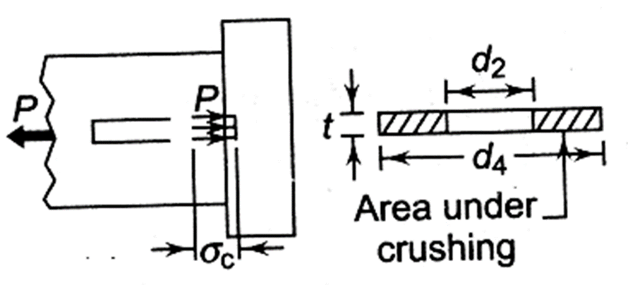
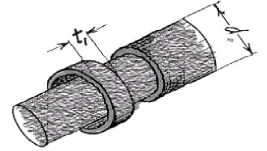
9. Crushing Failure of collar of Spigot and Socket [math]\frac{\pi }{4}{(d_3^2}-{d_2^2})\sigma_c=P[/math]
the spigot collar diameter is calculated from this relation.
10. Shear Failure of collar of spigot [math]{\pi }{d_2}{t_1}\tau=P[/math]
The collar thickness t is calculated from this relation.
Cotters may bend when driven into position. When this occurs, the bending moment cannot be correctly estimated since the pressure distribution is not known.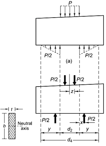
The force P between the cotter and spigot end is assumed as uniformly distributed over the length [math]{d_2}[\math].
The force between the socket end and cotter is assumed to be varying linearly from zero to maximum with triangular distribution.
[math]{x}=\frac{1 }{3}{y}=\frac{1 }{3}(\frac{d_4-d_2}{2})=\frac{1}{6}({d_4-d_2})[/math]
[math]{M_b}=\frac{P }{2}[\frac{d_2}{2}+{x}]-\frac{P}{2}{(z)} [/math]
[math]{M_b}=\frac{P }{2}[\frac{d_2}{2}+{\frac{1}{6}({d_4-d_2})}]-\frac{P}{2}{[\frac{d_2}{4}]}[/math]
[math]{M_b}=\frac{P}{2}{[\frac{d_2}{4}+\frac{d_4-d_2}{6}]}[/math]
Also [math]{I}=\frac{tb^3}{12}[/math], [math]{}y=\frac{b}{2}[/math] and [math]{\sigma_b}=\frac{(M_b)y}{I}[/math] therefore [math]{\sigma_b}=\frac{\frac{P}{2}{[\frac{d_2}{4}+\frac{d_4-d_2}{6}]}{\frac{b}{2}}}{\frac{tb^3}{12}}[/math]
[math]{\sigma_b}={3P}\frac{{[\frac{d_2}{4}+\frac{(d_4-d_2)}{6}]}}{tb^2}[/math]
After determining all the parameters, finally check the bending stress of the cotter using the above relation. If [math]{\sigma_b}<={\sigma_t} [/math], then design is safe; otherwise, design is failed.
[math]{\sigma_b}[/math] can be reduced by changing the value of t and b, since [math]{\sigma_b}[/math] is inversely proportional to the product [math]{tb^2}[/math].
It is more convenient to increase the value of b as compared to t (since it increases squarely).
After calculating new values of t and/or b from above, put these values in equations involving t and/or b and determine working stresses. If working stresses are less than or equal to the permissible stress of the material, then values are okay; otherwise, determine other parameter values from these relations.
click here to watch the video lecture
Tightening of the cotter introduces initial stresses, which are again difficult to estimate. Sometimes, therefore, it is necessary to use empirical proportions to design the joint. A design based on empirical relations may be checked using formulas based on failure mechanisms.
Design of Sleeve Cotter Joint
If the allowable stresses in tension, compression, and shear for the socket, rod, and cotter are σt, σc, and τ, respectively, assuming that they are all made of the same material, we may write the following failure criteria: [PDF]
1. Tension Failure of rod at diameter d [math]\frac{\pi }{4}{d^2} \sigma_t=P[/math] Determine d from this equation. 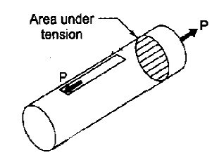
2. Tension Failure of rod across the slot [math](\frac{\pi }{4}{d_2^2}-{d_2}{t})\sigma_t=P[/math]  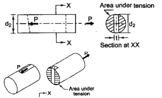
3. Crushing Failure of rod or cotter [math]{d_2}{t}\sigma_c=P[/math]
From above two equations, calculate d2 and t.
4. Tension failure of the sleeve across the slot. [math]\{\frac{\pi }{4}({d_1^2}-{d_2^2})-({d_1}-{d_2}){t}\}\sigma_t=P[/math]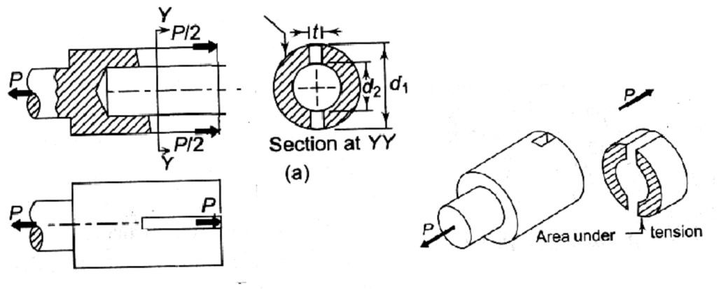
calculate d1 from this relation by putting the value of d2 and t.
5. Shear Failure of Cotter [math]{2}{b}{t}\tau=P [/math]
The value of b, i.e., the mean width of cotter, is determined from this relation.
6. Shear Failure of Rod end [math]{2}{a}{d_2}\tau=P [/math]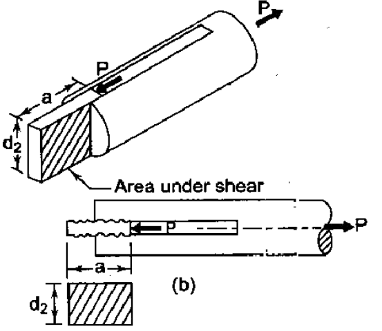
The value of a is determined by this relationship.
7. Shear Failure of Sleeve end [math]{2}{c}{(d_1-d_2)}\tau=P [/math]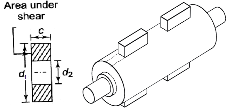
This relation is used to calculate the value of c after putting in the value of d1.
8. Crushing Failure of Sleeve or cotter [math]{(d_1-d_2)}{t}\sigma_c=P [/math]
calculate d1 from this relation.
Cotters may bend when driven into position. When this occurs, the bending moment cannot be correctly estimated since the pressure distribution is not known.
The force P between the cotter and sleeve end is assumed to be uniformly distributed over the length [math]{d_2}[\math].
The force between the sleeve end and cotter is assumed to be varying linearly from zero to maximum with triangular distribution.
[math]{\sigma_b}={P}\frac{{[\frac{d_2}{4}+\frac{d_1}{2}]}}{tb^2}[/math]
After determining all the parameters, finally check the bending stress of the cotter using the above relation. If [math]{\sigma_b}<={\sigma_t} [/math], then design is safe; otherwise, design is failed.
[math]{\sigma_b}[/math] can be reduced by changing the value of t and b, since [math]{\sigma_b}[/math] is inversely proportional to the product [math]{tb^2}[/math].
It is more convenient to increase the value of b as compared to t (since it increases squarely).
After calculating new values of t and/or b from above, put these values in equations involving t and/or b and determine working stresses. If working stresses are less than or equal to the permissible stress of the material, then values are okay; otherwise, determine other parameter values from these relations.
click here to watch the video lecture
Tightening of cotter introduces initial stresses, which are again difficult to estimate. Sometimes, therefore, it is necessary to use empirical proportions to design the joint. A design based on empirical relations may be checked using formulas based on failure mechanisms.
Design of Gib Head Cotter Joint
Consider a gib and cotter joint for square rods, as shown in the figure below.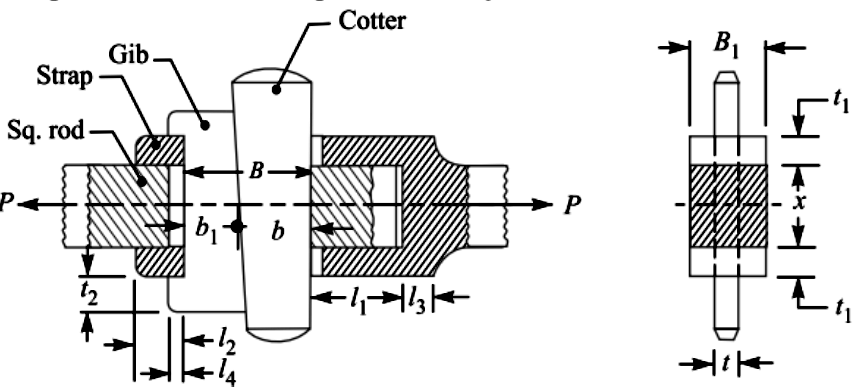
All components of the joint are assumed to be of the same material. If the allowable stresses in tension, compression and shear for all the components are [math]{\sigma_t}, {\sigma_c} [/math] and τ, respectively,
Let P = Load carried by the rods,
x = Each side of the rod,
B = Total width of gib and cotter,
[math]{B_1}[/math] = Width of the strap,
t = Thickness of cotter,
[math]{t_1}[/math] = Thickness of the strap: [PDF]
1. Tension Failure of rod at square end x. [math]{x^2} \sigma_t=P[/math] Determine x from this equation.
2. Tension Failure of rod across the slot [math]({x^2}-{x}{t})\sigma_t=P[/math] 
3. Crushing Failure of rod or cotter [math]{x}{t}\sigma_c=P[/math]
From above two equations, calculate x and t.
4. Tension Failure of the strap or fork end across the slot. [math]{2}({x}{t_1}-{t}{t_1})\sigma_t=P [/math] or [math]{2}{t_1}({x}-{t_1})\sigma_t=P[/math]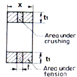
calculate t1 from this relation by putting the value of x and t.
5. Compression / Crushing Failure of Strap or Fork across slot [math]{2}{t}{t_1}{\sigma_c}=P [/math]
6. Shear Failure of Gib and Cotter [math]{2}{B}{t}\tau=P [/math]
The value of B, i.e., the mean width of cotter and gib, is determined from this relation.
7. Tension Failure of Strap or Fork at the weakest section [math]{2}{x_t}{\sigma_t}=P[/math]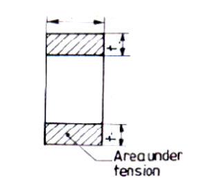
8. Shear Failure of Rod end [math]{2}{l_1}{x}\tau=P [/math]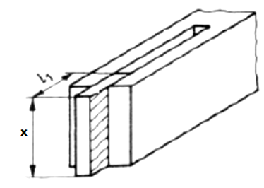
The value of l1 is determined by this relationship.
9. Shear Failure of strap or fork end [math]{4}{l_2}{t_1}\tau=P [/math]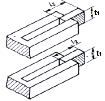
This relation is used to calculate the value of c after putting in the value of l2.
click here to watch the video lecture.
References
-
ABDULLA SHARIF, Design of Machine Elements, Dhanpat Rai Publications (P) Ltd, New Delhi, 1995.
-
http://www.nptel.iitm.ac.in
-
https://machinedesign.top/content/Introduction%20to%20Machine%20Design
-
V. B. Bhandari, Design of Machine Elements, Third Ed., The McGraw-Hills Companies, New Delhi
-
S. KHURMI and J.K.GUPTA, A Text Book of Machine Design, S. Chand and company ltd., New Delhi, 2000.
Q & A
Q. 1. Two rod ends of a pump are joined by means of cotter joints, making spigot & socket at the ends. Design the joint for an axial load of 50 kN which is alternately tensile and compressive.
Ans: click here to watch the solution in the video lecture.
Q. 2. Two rod ends of a pump are joined by means of a sleeve and cotter joint. Design the joint for an axial load of 40 kN which is alternately tensile and compressive.
Q.3. Design & draw a gib & cotter joint to resist a safe tensile load of 50 KN. The material of the gib, cotter & rod is same for which the allowable safe stress are σt = 25 N/mm2, σs = 20 N/mm2 & σc = 60 N/mm2.
